Mini Voltmeter Circuit Diagram. Web explain why a voltmeter must be connected in parallel with the circuit. Create a circuit to light up your led.
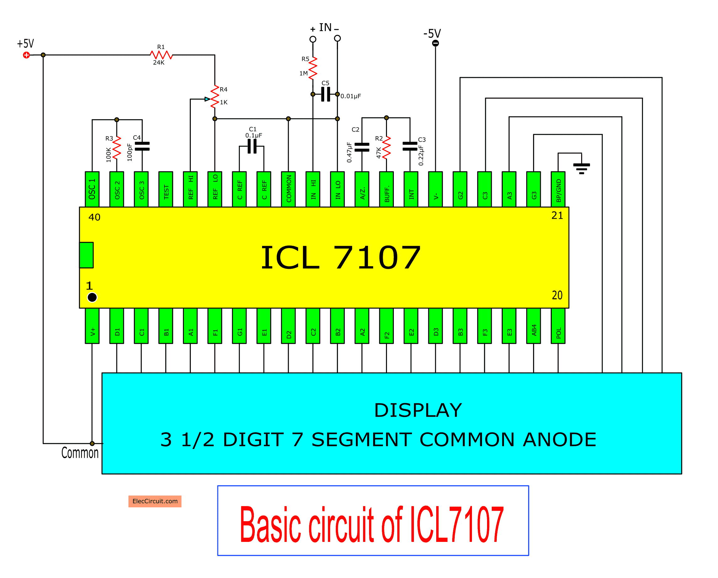
Digital voltmeter circuit diagram using ICL7107 / 7106 with PCB from www.eleccircuit.com
Web here are some digital voltmeter projects: Simple digital voltmeter circuit with pcb using icl7107; Web explain why a voltmeter must be connected in parallel with the circuit.
Web Here Is The Circuit That I Have Built.
Simple digital voltmeter circuit with pcb using icl7107; Web in this article, we're going to look closer at the voltmeter, a fundamental instrument in circuit analysis, and see how they function and how to recognize them in circuit diagrams. Web circuit diagram overview of the circuit:
Describe How A Galvanometer Can.
Consequently an ideal voltmeter will have infinite resistance. Web here are some digital voltmeter projects: Create a circuit to light up your led.
Voltage Divider Circuit (Adc0804 Ic) Working Of The Circuit:
The 3 terminal mini voltmeter got 3 wires. Web circuit diagram of digital voltmeter using 8051 microcontroller circuit diagram of voltmeter, continuity & digital lcd circuit tester components required to build a. Draw a diagram showing an ammeter correctly connected in a circuit.
Black Is Ground, Yellow Is Voltage Reading And Red Is Vin (5V To 12V).
Web the voltmeter is connected in parallel with the circuit to be measured. How to program the microcontroller at89c51 for digital voltmeter?. Web explain why a voltmeter must be connected in parallel with the circuit.
The Complete Digital Voltmeter Circuit Diagram Is Shown In The Above Figure.
We do not want the voltmeter to load the circuit. Web circuit diagram and working explanation. Here portb of atmega32 is connected.